USB TO UART/I2C/SPI/JTAG Adapter (25411)
USB TO UART/I2C/SPI/JTAG Adapter (25411)
SKU: 2688
Couldn't load pickup availability
| Warranty 12 months. Return or exchange within 14 days → | |
| Delivery Nova Poshta to branch/locker or courier to your address → | |
| Payment Pay on delivery or prepayment → |
Description

Key Features
- Supports USB → 2-channel UART, or USB → 1-channel UART + 1-channel I2C + 1-channel SPI, or USB → 1-channel UART + 1-channel JTAG
- 2-channel high-speed UART up to 9 Mbps, hardware flow control CTS and RTS
- 1-channel I2C — convenient control of EEPROMs from PC or programming of I2C devices (OLEDs, sensors, etc.)
- 1-channel SPI with 2 chip select (CS) signals — simultaneous control of two SPI devices
- 1-channel JTAG — compatible with OpenOCD for debugging and testing (functionality recommended for self-verification)
- Built-in 3.3V / 5V level shifting circuit — switchable via DIP switch on the board
- Built-in self-recovering fuse and ESD protection — protection against overcurrent and overvoltage
- Aluminum alloy casing with a matte finish, CNC processed — durable and long-lasting
- High-quality USB-B and DC connectors with reverse connection protection

Technical Specifications
| Host Interface | USB | |
|---|---|---|
| Power Supply | USB port, 5V | |
| Operating Level | 3.3V / 5V (selectable via DIP switch on board) | |
| USB | Connector | USB-B |
| Interface Protection | Self-recovering fuse, ESD protection | |
| UART | Number of Channels | 2 (red DIP switch in M0 mode) |
| Connector | 6-pin IDC | |
| Baud Rate | 1200 baud — 9 Mbps | |
| Hardware Flow Control | CTS and RTS | |
| I2C | Number of Channels | 1 (DIP switch in M1/M2 mode) |
| Connector | 12-pin IDC (first 4 pins — I2C) | |
| SPI | Number of Channels | 1 (DIP switch in M1/M2 mode) |
| Connector | 12-pin IDC (last 8 pins — SPI) | |
| JTAG | Number of Channels | 1 (DIP switch in M3 mode) |
| Connector | 12-pin IDC (last 8 pins — JTAG) | |
| Dimensions | 86.0 × 48.0 × 27.6 mm | |
Main Function
Convenient control and debugging of various interface devices via PC. Supports USB → 2-channel UART, or USB → 1-channel UART + 1-channel I2C + 1-channel SPI, or USB → 1-channel UART + 1-channel JTAG.

Operating System Support
Supports Windows 7 / 8 / 8.1 / 10 / 11, Linux, and other OS.

Application Areas
Suitable for engineering students, engineers, radio amateurs, and DIY enthusiasts for learning and device debugging.

Support for various interfaces
Multiple interfaces for debugging, most of which can be used simultaneously

Compact and convenient installation
Flexible installation, suitable for various devices

Provided mounting holes
Easy installation, industrial metal casing, sturdy and durable
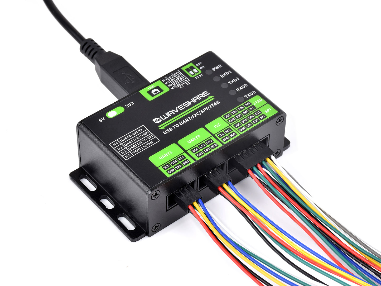
Description of Interfaces and Operating Modes


Indicators
| PWR | Power indicator — lights up when USB is connected and voltage is present |
|---|---|
| RXD1 | UART1 Receive Indicator — lights up when the device sends data back |
| TXD1 | UART1 Transmit Indicator — lights up when the USB port sends data |
| RXD0 | UART0 Receive Indicator — lights up when the device sends data back |
| TXD0 | UART0 Transmit Indicator — lights up when the USB port sends data |
Appearance

Dimensional Drawings

* Dimensions are measured manually. A permissible error of approximately 1 mm applies.
Resources and Support


* Resources may vary depending on the product. Please check the Wiki page for available materials.
Description
Key Features
- Supports USB → 2-channel UART, or USB → 1-channel UART + 1-channel I2C + 1-channel SPI, or USB → 1-channel UART + 1-channel JTAG
- 2-channel high-speed UART up to 9 Mbps, hardware flow control CTS and RTS
- 1-channel I2C — convenient control of EEPROMs from PC or programming of I2C devices (OLEDs, sensors, etc.)
- 1-channel SPI with 2 chip select (CS) signals — simultaneous control of two SPI devices
- 1-channel JTAG — compatible with OpenOCD for debugging and testing (functionality recommended for self-verification)
- Built-in 3.3V / 5V level shifting circuit — switchable via DIP switch on the board
- Built-in self-recovering fuse and ESD protection — protection against overcurrent and overvoltage
- Aluminum alloy casing with a matte finish, CNC processed — durable and long-lasting
- High-quality USB-B and DC connectors with reverse connection protection
Technical Specifications
| Host Interface | USB | |
|---|---|---|
| Power Supply | USB port, 5V | |
| Operating Level | 3.3V / 5V (selectable via DIP switch on board) | |
| USB | Connector | USB-B |
| Interface Protection | Self-recovering fuse, ESD protection | |
| UART | Number of Channels | 2 (red DIP switch in M0 mode) |
| Connector | 6-pin IDC | |
| Baud Rate | 1200 baud — 9 Mbps | |
| Hardware Flow Control | CTS and RTS | |
| I2C | Number of Channels | 1 (DIP switch in M1/M2 mode) |
| Connector | 12-pin IDC (first 4 pins — I2C) | |
| SPI | Number of Channels | 1 (DIP switch in M1/M2 mode) |
| Connector | 12-pin IDC (last 8 pins — SPI) | |
| JTAG | Number of Channels | 1 (DIP switch in M3 mode) |
| Connector | 12-pin IDC (last 8 pins — JTAG) | |
| Dimensions | 86.0 × 48.0 × 27.6 mm | |
Main Function
Convenient control and debugging of various interface devices via PC. Supports USB → 2-channel UART, or USB → 1-channel UART + 1-channel I2C + 1-channel SPI, or USB → 1-channel UART + 1-channel JTAG.
Operating System Support
Supports Windows 7 / 8 / 8.1 / 10 / 11, Linux, and other OS.
Application Areas
Suitable for engineering students, engineers, radio amateurs, and DIY enthusiasts for learning and device debugging.
Support for various interfaces
Multiple interfaces for debugging, most of which can be used simultaneously
Compact and convenient installation
Flexible installation, suitable for various devices
Provided mounting holes
Easy installation, industrial metal casing, sturdy and durable
Description of Interfaces and Operating Modes
Indicators
| PWR | Power indicator — lights up when USB is connected and voltage is present |
|---|---|
| RXD1 | UART1 Receive Indicator — lights up when the device sends data back |
| TXD1 | UART1 Transmit Indicator — lights up when the USB port sends data |
| RXD0 | UART0 Receive Indicator — lights up when the device sends data back |
| TXD0 | UART0 Transmit Indicator — lights up when the USB port sends data |
Appearance
Dimensional Drawings
* Dimensions are measured manually. A permissible error of approximately 1 mm applies.
Resources and Support
* Resources may vary depending on the product. Please check the Wiki page for available materials.